I completed two seperate projects this week to gain experience with 3D design/printing and 3D scanning.
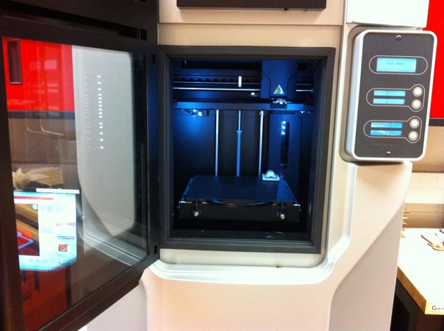
I used a Dimension 1200es at the Mott Community College Fab Lab for the fabrication of this part.
The part is to be used as the spacer for a 6 part gang programmer for ATTiny10 MCUs.
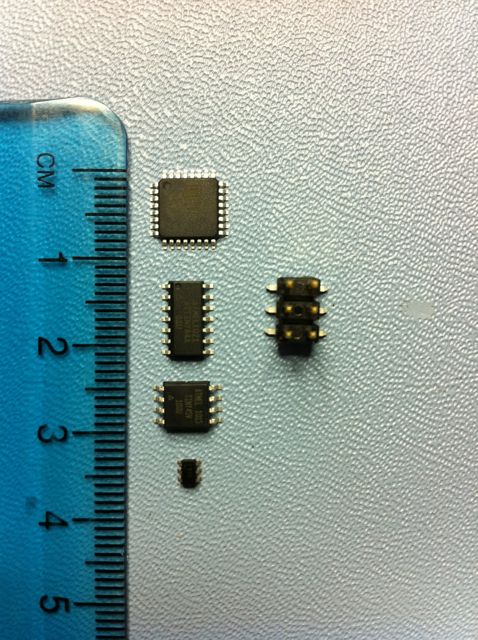
Here is a picture of the family of AVR propcessors in the Fab Lab inventory plus an ATTiny10 at the bottom. At the top is a Mega168/328 processor, next is a Tiny44, third is a Tiny45, and at the bottom is the Tiny10. As you can see the Tiny10 is tiny!
The picture also shows the 6 pin connector normally used for in circuit programming of the embedded ATTinu MCUs on the right. The connector itself is as large as some of the entire circuit boards that might use the Tiny10.
In order to maintain a small board size I would like to program the processor before putting it onto the board. As the processors are very samll and hard to handle I would like to be able to program a batch of them at a time.
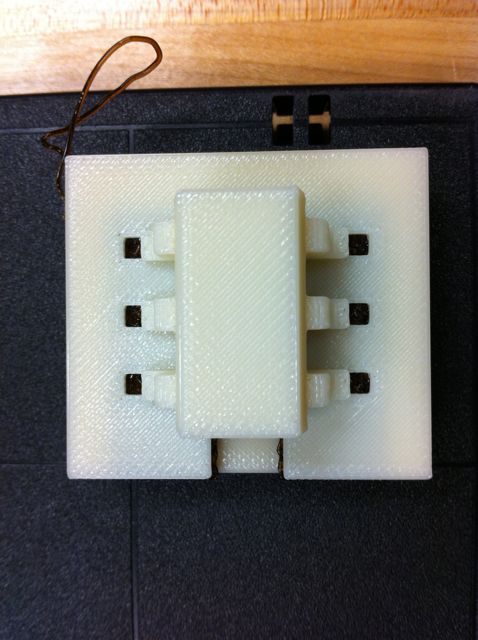
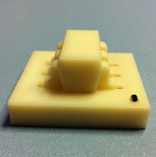
The part that I designed and 3D printed spaces 6 ATTiny10 MCUs on a circuit board with traces positioned to make contact with the processor pins when the processor is pressed against the board.
The board is inserted in a slot in the part with a central channel high enough to support the MCU and components necessary to switch 12V to the processor reset pins based upon serial commands over a FTDI interface .
I designed the part using OpenSCAD - OpenSCAD file.
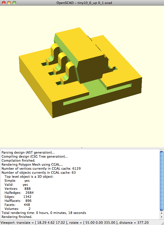
It was exported to a text STL file.
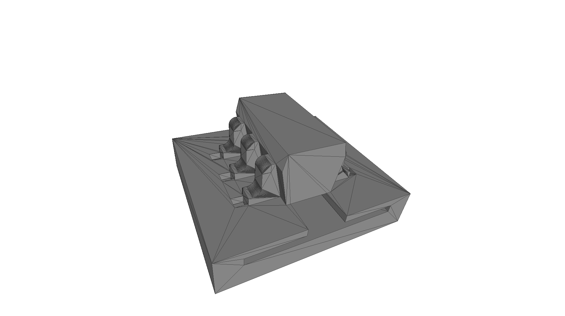
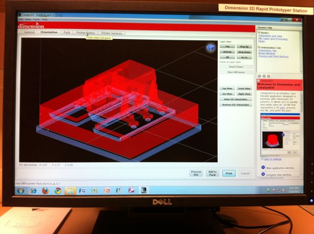
After checking the part with MeshLab it was imported into the CatalystEX software to process for building on the Dimension printer.
Part in Dimension 1200es printer.
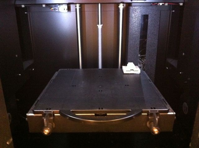
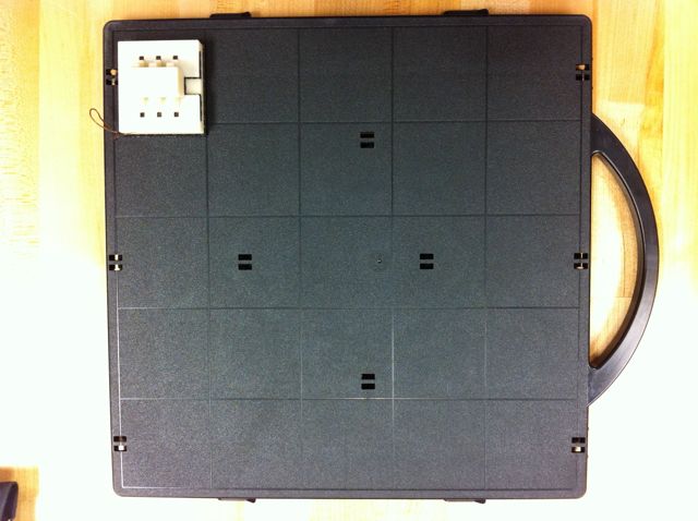
Part prior to separation from platform.
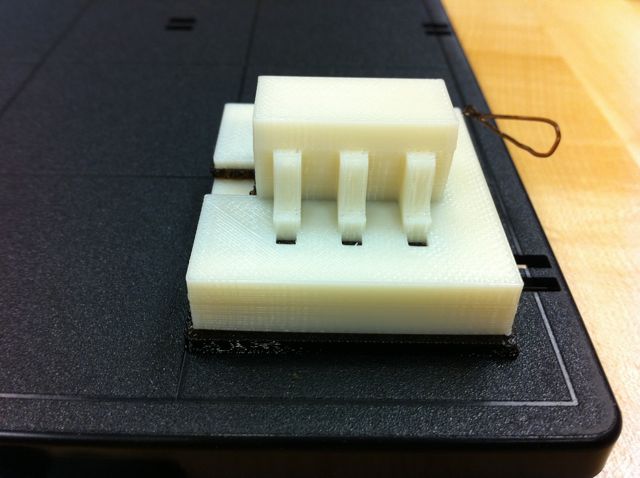
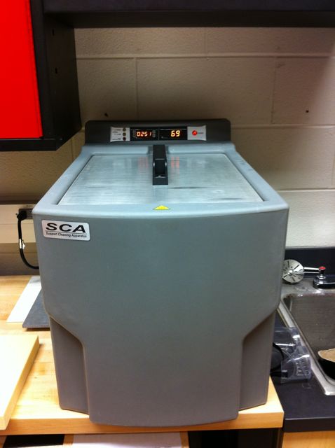
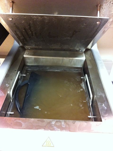
Dissolving the support material from part.
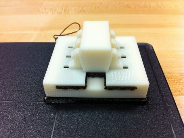
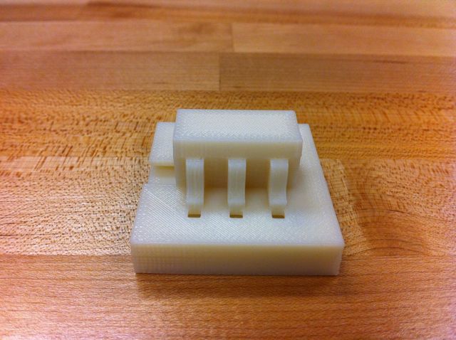
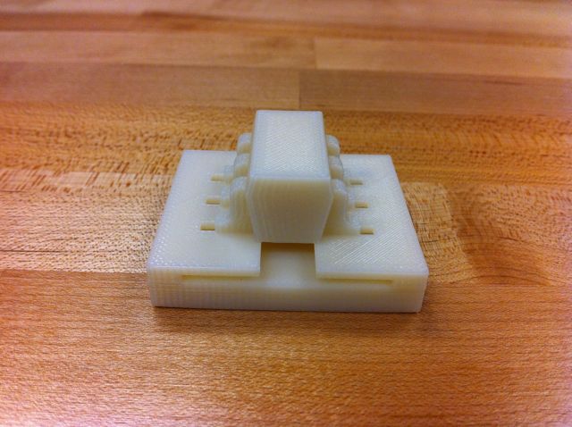
Finished part.
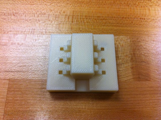
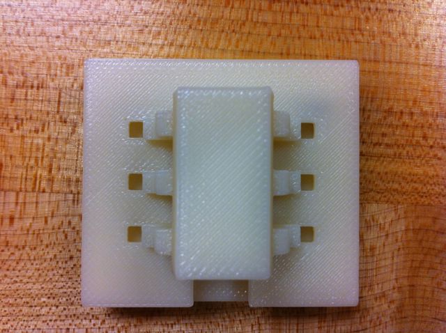
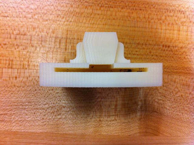
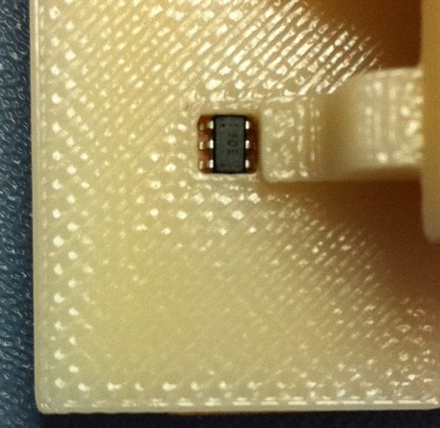
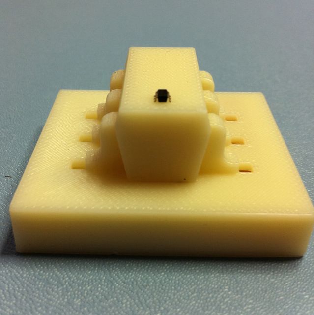
A processor positioned in one of the 6 programming pockets.
The top part of the object serves not functional purpose with programming but was intended to reflect the shape of the processors to be programmed.
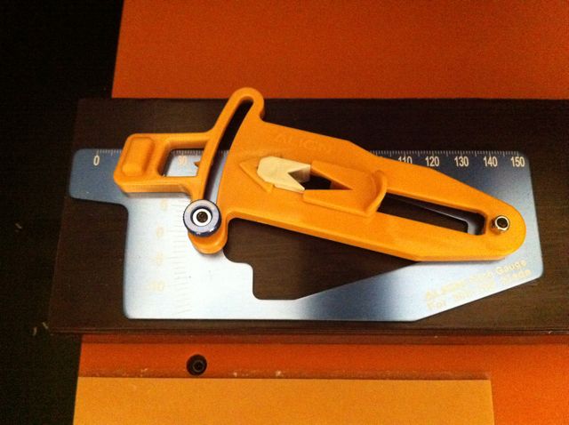
I used the scanning head (ZSC-1) on the Modela mill to scan a tool used for measuring the incidence angle of model helicopter blades.
 .
.
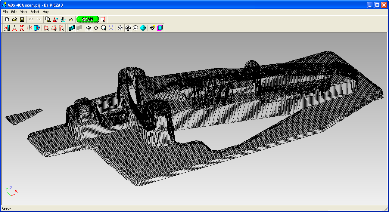
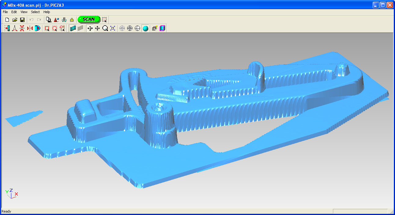
Here is the compressed STL file from the scan. The scan took over 15 hours!
The resulting scan in wireframe and surface rendering in the Roland Dr Picaza3 program.
I think that I will continue to explore other scanning options for future needs.